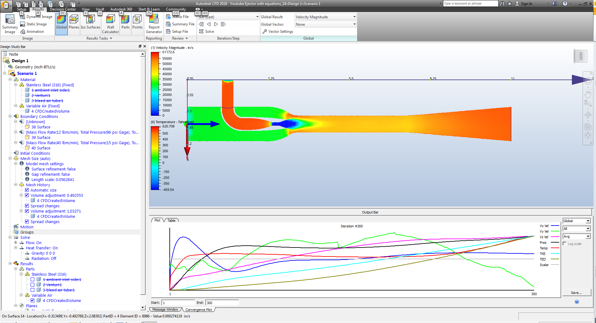
Jul 01, 2019 Ejector Design Calculation; Steam Ejector Design Calculation; Ejector Design Calculations; Online Ejector Screening process Software Transvac designers have created an on the internet. The most comprehensive source of design information for ejectors can be found in a series of Engineering Sciences Data Unit (ESDU) data items, Nos. 85032 and 84029. 6 Design of new ejector and comparison with measured ejector We will find the new ejector which has greater mass flow rate in the suction branch (mass flow of air) than the original.
The basic SI unit of force is the newton, which has the symbol N.One newton is defined as the force necessary to give a mass of 1 kg an acceleration of 1 m/s2. The acceleration due to gravity is normally taken as 9.81 m/s2. This is the acceleration imparted to a 1 kg force by its own weight (1 kg-force). Hence:
1 kg-force = 9.81 N
1 tonne-force = 9810 N or 9.81 kN
Note: For less precise calculations the value of g is often taken as 10 m/s2. The SI unit of pressure and stress is the pascal, which has the symbol Pa.
1 Pa = 1N/m2
1MPa= 1 MN/m2 or 1 N/mm2
1 GPa = 1 GN/m2 or 1 kN/mm2
Note: The SI system actually uses the designation 9/81 ms–2 for the acceleration of gravity (g) and a similar system for other units. However, to avoid confusion the traditional
designation is being used here.
Formulae
The following formula may be used for calculating the ejection force:
This is the way the formula is usually written in scientific texts but a slightly easier form for computational purpose is:
where:
Fp = the ejection resistance force (N)
E = Young's modulus of the polymer (N/cm2)*
A = total surface area of moulding in contact with cavity or core, in line of draw (cm2)*
μ= coefficient of friction, polymer on steel
m = Poisson's ratio
d = the diameter of a circle whose circumference is equal to the total projected perimeter of the moulding (cm)*
∝= the coefficient of linear expansion of the polymer (cm/°C)*
Δt= (polymer softening temperature) (mould tool temperature) (°C)
t = average wall thickness of part (cm)*
*Note that the units of length here are all in cm.
Example
A two-impression thin walled box-shaped component is to be moulded on a 275 tonne press. The machine has an ejector force rated at 40 kN. Calculate whether this is sufficient given the following data:
Brilliant database ultimate crack. Material: Polystyrene (PS)
Young's modulus of elasticity: 300,000 N/cm2
Poisson's ratio: 0.35
Coefficient of friction (PS on steel): 0.4
Softening temperature of PS: 80 °C
Mould tool temperature: 20 °C
Coefficient of linear expansion (PS): 0.00007 cm/°C
The dimensions of the box are shown in Figure 10.8: all dimensions are in cm.
Total area of resistance = 2 x (12 x 15) + 2 x (12 x 25) = 360 + 600 = 960 cm2
Total projected perimeter = 2 x 15 + 2 x 25 = 80 cm
Hence:
d = 80/π = 25.46 cm and Δt = 80 20 = 60 °C
Therefore,
Steam Ejector Design Calculation
p F = 13 824 N, or 13.8 kN
Hence for a two-impression tool we require 2 x 13.8 kN = 27.6 kN. This is well within the machine specification of 40 kN; however, in practice the machine ejection force will also be subject to the sliding resistance of the ejector system and sometimes to force
exerted by any return springs used in the ejector assembly.
Ejector Design Calculation
A good rule of thumb is to apply a factor of 1.25 for nonspring systems and 1.5 for spring return systems. Therefore, in this case the total ejection resistance force is:
1.25 X 27.6 = 34.5 kN for non-spring systems, or
1.5 X 27.6 = 41.4 kN for spring return systems
This demonstrates that the machine ejection force is satisfactory for the first case but unsatisfactory for the second case.
Please contact me if you would like a excel spread sheet for this calculation.
